ABLETM
Advanced Bindery Library
Exchange
Reference
Guide
Volume 12
Embosser Control
Version 6.6.1
June 9, 2003
ABLEä Ventures, LLC
Copyright by ABLEä Ventures, LLC
This reference guide is copyrighted and all rights are
reserved. This document may not, in
whole or in part, be copied, photocopied, reproduced translated, reduced to any
electronic medium or machine readable form without prior consent, in writing,
from the ABLEä
Ventures, LLC.
The information in this document is subject to change without notice. The ABLEä Ventures, LLC assumes no responsibility for errors that may appear in this document.
For more information visit the ABLEä web site: http://www.programmingconcepts.com/able/
Or contact,
ABLEä Ventures, LLC
c/o Paul Parisi
ACME Bookbinding
(800) 242-1821
For technical support contact:
Programming
Concepts, Inc.
web site: http://www.programmingconcepts.com/able/
e-mail: able_support@programmingconcepts.com
telephone: 631-563-3800 x230
fax: 631-563-3898
ABLEä
Ventures, LLC
Acme Bookbinding
Information Conservation, Inc.
Kater-Crafts Bookbinders
Lehmann Bookbinding
Mekatronics Inc.
National Library Binding of Georgia
Ocker & Trapp Library Bindery Inc.
Programming Concepts, Inc.
ABLEä
is a trademark of Mekatronics, Inc. / Bendror International Inc. 1987-2001
3.1 Cloth Pulling Report (CPR) Labels
Appendix B
- Gem Communication Protocol -
Crestron
B.1.1 Notation and Conventions
B.2.2 START OF TITLE (Code = 201)
B.2.3 CHARACTER DATA (Code = 202)
B.2.4 END OF TITLE (Code = 203)
B.2.9 TIMED CHARACTER DATA (Code = 210)
B.2.10 SET LIGHTS (Code = 211)
B.2.12 ENCODER STATUS REQUEST (Code = 213)
B.3 GEM TO ABLE COMPUTER COMMANDS
B.3.3 HARDWARE SAFETY (Code = 222)
B.3.4 MOTION FAILURE (Code = 223)
B.3.6 START PRESSED (Code = 225)
B.3.7 MOTION TIME REPORT (Code = 226)
B.3.8 ENCODER STATUS REPORT (Code = 227)
Appendix C
- Gem Communication Protocol -
Galil
C.1.1 Notation and Conventions
C.2.2 START OF TITLE (Code: MC=1x)
C.2.3 CHARACTER DATA (Code: LD)
C.2.4 END OF TITLE (Code: MC=2)
C.2.7 EMBOSS/RESUME (Code: MC=5x)
C.2.8 TIMED CHARACTER DATA (Code: MC=6)
C.2.9 SET LIGHTS (Code: MC=7x)
C.2.11 ENCODER STATUS REQUEST (MC=9)
C.3 GEM TO ABLE COMPUTER COMMANDS
C.3.2 NOT ACKNOWLEDGED (Code: NAx)
C.3.4 START PRESSED (Code: SP)
C.3.5 MOTION TIME REPORT (Code: T#xxxxx)
C.3.6 ENCODER STATUS REPORT (Code: S#xx)
C.3.7 ERROR CODE (Code: ?#xxx)
Appendix D
- Gem Embossing Area Boundary
Appendix E
- Gem Power Up Command Sequence
Appendix F
- Gem Emboss A Piece Command
Sequence
Release Notes
V6.0 Preliminary release for review.
V6.01 Changes for ABLEä release 6.01.
V6.02 Changes for ABLEä release 6.02.
V6.4 Changed copyright.
The ABLEä Reference Guide is comprised of multiple volumes. The collection of volumes describes the functional and operational characteristics of ABLEä. The volumes are:
|
Volume |
Reference
Guide |
File Name |
|
1 |
r6-intro.htm |
|
|
2 |
Library User |
r6-library-user.htm |
|
3 |
r6-user.htm |
|
|
4 |
r6-title.htm |
|
|
5 |
R6-style.htm |
|
|
6 |
r6-report.htm |
|
|
7 |
r6-control.doc |
|
|
9 |
r6-maint.htm |
|
|
10 |
r6-transfer.htm |
|
|
12 |
R6-emboss.htm |
|
|
13 |
r6-help.htm |
|
|
15 |
r6-bill.htm |
|
|
16 |
r6-pm.htm |
|
|
19 |
R6-s3.htm |
|
|
20 |
r6-linstall.htm |
|
|
21 |
r6-binstall.htm |
|
|
22 |
r6-ezcut.htm |
|
|
23 |
r6-ftp.htm |
|
|
24 |
r6-alink.htm |
|
|
25 |
r6-zlink.htm |
|
|
27 |
r6-file-import.htm |
1. Introduction
The embossing services are those services used to prepare and control Jobs for embossing. The services include:
·
Release
·
Correct
Item/Piece Problems
·
Cloth
Pulling Labels
·
Initiate
Embossing
·
Monitor/Control
Embossing
· Embosser Diagnostics
ABLE/Bindery provides these functions in the following programs:
·
Title
Composition
·
Reports
· GETJOB (for the RB7/11 run from the RB7/11)
Figure 1 shows the configuration of ABLEä/Bindery with embossers.
Figure 1 - Embosser Configurations
The embosser support provided by ABLE/Bindery is as follows:
·
System 3 Type 2 S3 is controlled by S3 workstation.
· System 2 Type 1 S2 is sent file to emboss.
· GEM Type 2 GEM is control by dedicated ABLEä workstation.
·
RB7/11 Type 2 RB7/11 requests jobs from dedicated ABLEä
workstation.
The embossing services, associated programs, the computer where they are invoked, and the computer where they are processed are listed in Table 1.
Table 1 - Embosser Programs
|
Service |
Embosser |
Initiate |
Program |
|
Release and Correct |
S3 |
Title Comp |
. Title Comp |
|
Cloth Report Pulling (CPR) |
S3 |
Automatic |
Optional |
|
|
|
Report |
Report |
|
Job Summary Report |
S3 |
Automatic |
Optional |
|
|
|
WS |
Report |
|
Emboss Job |
S3 |
Title Comp |
S3 Workstation |
|
Monitor / Control Embosser |
S3 |
S3 Workstation |
S3 Workstation |
|
Job Emboss Status |
S3 |
S3 Workstation |
S3 Workstation |
Automatic initiation is optional for those services listed as Automatic in Table 1. The program that will cause the automatic service may be selected based on the service. For example, CPR may be initiated from the Measurement program.
2. Release Service
The Release service verifies that all of the Job Pieces are ready for embossing. If there is a text fitting or other problem the Piece is allowed to be corrected and the release process continued.
Releasing a Job is the next ABLEä Bindery processing step after measurement. All pieces in a Job must be measured prior to release. If a piece is not measured, an error will occur during the release process. There is also an automatic calculation option. If set, this option automatically calculates a piece's measurements during the release process.
The formatter/embosser to which the piece is text fit for is determined by the embosser type specified for the Job (i.e. GEM, RB7/11, System 2), and, for the System 2, the characteristics of the piece (e.g. font, pitch, print color).
Release is initiated using the Release option on the Tools menu bar selection
If an item in a Lot is released and the Lot has already been processed or produced, the Lot status is reset to "restored". This allows for the Lot Costing to be re-generated during the Automatic Lot Process and the history to be updated during the Automatic Lot Process or Diskette Production.
Release causes the titles in the current job to be checked for text fitting problems. Once no problems are detected the Job is available for embossing.
There are two types of titles that are not embossed. The first type is selected through the System Parameters service. A title whose class matches the "no emboss class" (see "noembcl" in System Parameters) is not embossed and does not have a cloth pulling report printed. Only one class can be selected for this special treatment. The titles with these classes are not sent to the embosser.
A title whose category matches the No CPR/Emboss or No Emboss category is not embossed. Also, a title whose category matches the No CPR/Emboss or No CPR category does not have a cloth pulling report printed. A title whose has a No Touch class is not embossed and does not have a cloth pulling report printed. (Refer to No CPR/Emboss, No CPR, and No CPR/Emboss fields in the Class and Category definitions in the File Maintenance Reference Guide.) .
The second type of title that is not embossed is a blank title. This is used to track a title through the bindery, and have cloth pulled, even though the embosser will not emboss the cover. This is usually for cloth that is to be hand embossed. These titles cause errors on the embosser and print cloth pulling reports. The errors on the embosser can be ignored once the cloth and the title are matched up.
Each Job piece is displayed on the screen. If the piece has been previously successfully text fitted (e.g. using the MSR automatic option), then the next piece of the Job is displayed without operator intervention. If it has not been text fitted then release will cause text fit to take place. If it is successful the next piece is displayed without operator intervention.
It is expected that only a very small per cent of the Job's pieces will not text fit. If there are no text fitting errors in the Job then the Job is ready for embossing.
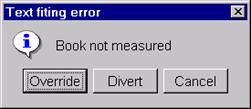
If there are errors an error message is displayed and the operator must correct the errors before ABLE will allow the Job to be released successfully. The operator is presented the following options (refer to the following figure):
·
Correct
the error
The piece can be edited to fix the problem. The operator can manually text fit the piece and then view the spine image to check if the problem has been corrected.
ABLE places the cursor at the point in the text where the error was detected, and a message describing the error is displayed on the screen. The operator should then modify the title data to correct the error.
Selecting Update cause the Piece record to be updated and the text fitting algorithm to be executed again. If the error was corrected, the process continues with the next error title.
·
Override
Override the error allowing release to continue. Only errors that do not have title text syntax errors may be released without a successful text fit. The Override button is used to initiate the processing.
The override selection results in a best attempt at providing a reasonable title for embossing. Once it arrives at the embosser, it may require editing to correct the problem discovered by ABLE.
There may be cases where the title is "close enough" and no editing is needed BUT there is no guarantee that ABLE has transferred the data as it is. This is because ABLE stops its text fitting/segment creation process when it discovers the first error. It makes no attempt at correcting the error nor does it continue checking the remainder of the title.
·
Divert
(to the "Error" Job)
Divert moves the Piece to the assigned "error" Job for this current Job. The error Job must have been previously defined for the Job using the Job screen. The Divert button is used to initiate the processing.
·
Cancel
Use the Cancel Release action button is used to cancel the release.
Caution
Be careful during Release that you don't inadvertently invoke the release function a second time. If you do, the current piece may not to be released properly which will result in unexpected embosser errors.
2.1 Auto Release
The Auto Release option allows jobs that are measured to automatically be released. With the “auto release” option in the Tools menu checked, error pieces are brought up on the client screen. The operator can choose the Override, Divert, or fix the piece.
Caution
When Auto Release is checked in the Tools menu, no other operations should be performed until an error piece is brought up on the screen.
The auto release process is handled by the ABLEä Auto Release system service in Windows NT/2000. By default, this process is not started after ABLEä Bindery is installed. To start this process, do the following:
q In Windows 2000, go the Control Panel and double click on “Administrative Tools”.
q Double click on Services. The name of the auto release service is “ABLE Auto Release”.
q Double click on “ABLE Auto Release”. In the “startup type” dropdown list choose “Automatic”, then click OK.
q Click on the “Play” button to start this service. The next time the system boots, this service will automatically be started.
3. Automatic Reports
There are automatic embosser related reporting services available after the successful Release of a Job. The primary reports you will utilize after Release are one or more of the following,
·
Cloth Pulling (CPR) Labels
·
Job Summary Report
·
Job Binding Slips
There are other reports that may be automatically invoked after Release. Refer to the Event – Action Table in the File Maintenance Reference Guide.
3.1 Cloth Pulling Report (CPR) Labels
This report prints cloth pulling labels in the order the job pieces are to be embossed. Refer to the Reports Reference Guide.
Recommendations: For the RB7/11, the CPR is automatically generated after all the pieces of a job are measured.
For the System 2, the report is automatically generated when a job is released to the System 2 (formatter or embosser). There are one or more CPR labels for a title. If there are multiple panels with changes in horizontal or vertical placement a second CPR label is printed.
Note: If a piece requires multiple copies, then multiple CPR labels are also printed.
Note: The cloth height and width are the calculated minimum cloth measurements. They are NOT the measurements of the pre-cut cloth indicated by the Cloth Bin number. Do not cut the cloth to these dimensions since the embosser is given the measurements of the cloth pulled from the bin.
3.2 Job Summary Report
The Job/Piece report is the same report as that selected from the Report program with the full set of measurements: Job (MSR). Refer to the Reports Reference Guide.
3.3 Job Slips Report
Slips will only be printed if a Piece's Account record has the "Print UBS" field set and the AutoProc UBS field not selected. Refer to the Reports and Maintenance Reference Guides for additional information about this report.
|
NOTE The report is printed BEFORE the Automatic Account Processing or Bindery Transfer Production phase. This means that the titles have not yet been updated nor created (if needed). The Job Slips may not be "perfect" depending on the circumstances. To obtain "perfect" slips, suspend the printing of job slips until the Automatic Account Processing phase. This can be done by selecting the "AutoProc UBS" field in the account record. Refer to the File Maintenance Reference Guide for additional information. |
4. Embosser Control Services
Embossing is initiated using the Emboss option on the Tools menu bar selection on the Title Composition screen.
The Embossing Control program provides the services necessary to prepare for embossing, embossing a Job, monitor/control embossing and diagnosing embosser problems. Every function is not available for every embosser type.
·
Emboss a Job / Piece GEM, System 3
· Emboss Queue Entry All embossers
· Divert/Override Piece All embossers
· Monitor/Control Embosser GEM
·
Emboss Status GEM
·
GEM Diagnostics GEM
·
Rush Piece GEM
·
Rush Job GEM
The User Parameters for GEM embossing are,
Select COM port (COM1 or COM2)
Select embosser type (GEM Crestron, GEM Galil)
Only the Item and Piece keys can be used when embossing.
A GEM unit may be monitored and controlled. Monitoring allows the operator to view every piece on the Title Composition screen as it is being embossed. Control allows the embosser unit to be stopped, resumed, reset, aborted, individual pieces embossed and diagnosed.
The operator must select Monitor mode in order to monitor and control an embosser unit. Release and editing cannot be initiated if Monitor mode is active.
The menu selections for Emboss are,
Emboss Job Emboss Job
Emboss Piece Emboss Piece
Embosser Queue Show Jobs Released and Embossing Started
Status Show Embosser Status
Stop Stop Embossing Job
Resume Continue Embossing Job
Abort Abort Embossing Job
Reset Reset Embosser
GEM Diags High Test Pattern Diagnostic
GEM Diags Low Specific GEM Commands
Stop Stop embossing Job
- Emboss Job
The current Job is embossed for the selected type of embosser. The current Job is selected either by: (a) using the Job screen to enter the Job Id, or (b) using the "Queue" list of Jobs to select the current job (see below).
Note: Pieces with "copies" values greater than 1 will be embossed "copies" times.
For the GEM,
This function causes a Job to be embossed, monitored and controlled. Each Piece is first displayed (i.e. monitored) before it is embossed. Any problems, as per the Release, will be displayed. If Release is used, there should be no problems encountered. Only one Job can be released at a time to the GEM. This process continues without operator intervention until a problem is encountered. Any detected error causes the embossing to stop until the operator corrects the error at (a) the workstation and continues (Resume) or (b) selects how to deal with the problematic piece and continues (Resume).
Each piece of the Job is displayed before it is embossed. The GEM operator can control the embossing process at the GEM using the Stop, Resume, Abort and Reset services.
Jobs can be sent for embossing at any time using the Job selection. If monitoring is active then only the monitored embosser unit can be sent a new Job to emboss. The operator must select the none-Monitor mode before a Job can be sent to a different embosser unit.
There are three conditions causing the embossing of a Job to stop: (a) the program detects an error condition, (b) the workstation operator selects "Stop" during monitor mode, and (c) the GEM operator selects "Stop". While in monitor mode, the status is automatically displayed. But, if monitor mode is not active, you must enter monitor mode to determine the problem.
Once stopped, the process can be resumed or aborted while in monitor mode. A Resumed Job starts from the piece currently being displayed. In the case of an error, the entire piece is started from the beginning (i.e. a new piece of cloth may be needed).
For System 3
This function causes a System 3 title file to be produced in a specified directory on the file server. See Volume 19 (System 3 Services) for additional information.
- Emboss Piece
The Piece service embosses the piece currently being displayed. This selection is only valid if the embosser is being monitored and is not currently embosssing a piece or executing a diagnostic.
For the GEM
This function sends the Piece to be embossed, to the currently selected embosser/unit, that is currently being monitored. Note: Emboss Piece causes the piece to be embossed only once regardless of its "copies" value. Use Resume Job to re-emboss pieces "copies" times.
For System 3
This function creates a System 3 title file containing just one piece. See Volume 19 (System 3 Services) for additional information.
- Embosser
Status (GEM)
This selection displays the status of the GEM embosser being monitored. The last error status is displayed. This status may be the current problem or the last problem that was corrected.
- Embosser Queue
This function displays a list of all Jobs ready to be
embossed and currently being embossed.
For the System 2, individual parts of Jobs may be listed depending on
the characteristics of the System 2.
These are the jobs that have been:
(a) Released (Job Status = REL)
(b) Embossing
Started (Job Status =
Once the operator finds the job to be processed, that job can be selected for embossing from this screen.
The status information for each Job includes the Job Id, Job Status (released, embossing started), the date the job was created, and the embosser type (i.e. GEM). The embosser unit is a future option.
- Embosser
Status (GEM)
The current state of the embosser being monitored is displayed. The Embosser states are grouped into normal, error, and diagnostic states:
Normal States: Emb On Line
Waiting for Start
Embossing
Error States Emb Off Line
Motion Error
Safety Error
General Error
Diagnostic States: Timing Report
Encode Report
Definitions of each state are provided below in the GEM Embossing section.
- Stop (GEM)
Stops the GEM Embosser during the emboss process.
Note: Unless the condition causing the problem is corrected the Stop command may not be recognized until the built in time-out period expires (about 5 minutes). The command may not be processed since the embossing of the Piece must be completed before the Stop is processed.
- Resume (GEM)
This menu selection causes the current Piece (the one on display), that was previously stopped, to continue. Monitor mode must be active.
This function allows multiple Jobs to be stopped and then resumed. An example of its use would be to suspend the current Job while a rush Piece or Job is embossed. The suspended Job can then be resumed where it left off.
- Abort (GEM)
This menu selection aborts the embossing process. Once aborted, the process can NOT be re-started by selecting "Resume".
Note: Unless the condition causing the problem is corrected the Abort command may not be recognized until a built in time-out period expires (about 5 minutes).
- Reset (GEM)
This menu selection resets and re-initializes the GEM embosser unit being monitored.
- GEM Diagnostics
These menu choices allow the execution of the GEM diagnostics for the GEM unit being monitored. There are two selections:
High Level Test (Test Pattern Embossing
Tests)
Low Level Test (Technician Tests)
A High Level Test automatically performs a general set of diagnostics which checks if the GEM is in working order and is communicating with the Embosser Control program. The user is prompted to insert a cloth for test embossing on the GEM. The results are a visible embossed pattern which can be viewed to see if the embossing is working to specification. Any other errors encountered are displayed and the diagnostic is aborted.
The Low Level Test allows GEM service personnel to execute individual GEM operations. If this option is chosen, a screen will be displayed with the low level commands available for execution. Refer the Low Level Diagnostic Appendix for directions for using the diagnostic.
5. Embosser Services
The embossing control services are described by embosser type:
·
System 3
·
RB7/11
·
System 2
·
GEM
5.1 System 3 Embossing
See the System 3 Services guide (Volume 19) for details on Embossing with the System 3.
5.2 RB7/11 Embossing
For the RB7/11 Embosser, the Job is embossed by requesting the Job at the embosser's terminal (executing " @getjob"). The pieces are then transferred to the RB7/11. The operator then embosses the Job. If necessary individual pieces can be edited at the RB7/11 before embossing. In addition, a rush job service is also provided that allows selected jobs to be place at the head of the embossing queue.
The command sequences need to use getjob or rush are as follows:
1. Place the "getjob"/"rush" diskpack into (the primary) drive 0 of the appropriate RB7. (Note: Boot the RB7 if not already booted.)
2. Execute the getjob (or rush) program by enterring the following command at the dot prompt.
.@GETJOB {for getjob}
or
.@RUSH {for rush}
3. The "getjob" (or "rush") program initially displays informational data such as CSR, Vector, HT code and WT code. It then "cleans up" (bypassed for "rush") the disk during what is called "PHASE 1". After completion of "PHASE 1", the program enters "PHASE 2" and displays the prompt:
Enter Job Id ['quit' to quit] : "
The user is then expected to enter the Job Id of the job to be transferred (or rushed if running "rush") from the VAX to the RB7.
Note 1: Once "rush" is executed for a RUSH job, DO NOT start getjob until the rush job has been embossed. If you execute getjob before a rush job has been embossed, the emboss queue may be rearranged and the priority job may not remain the highest priority job.
Note 2: Type the command @RB7 (or @GEM) to restart the UBS program after using getjob (or "rush").
Multiple embossers can be supported by the using one ABLEä workstation per RB7/11 with separate serial transmission lines.
An alternative configuration option is to have one RB7/11 computer online with the host and using this computer to execute getjob. The pieces are placed onto the removable disk. The disk is then moved to one of the RB7/11's with embossing capabilities. This allows maximum utilization of the embossers.
It is important that the fonts on the RB7/11 exactly match the fonts on ABLE. If there is a difference the title will not emboss as you expect. Be sure to carefully check the font characters for each RB7/11 wheel.
The "Set Of" service is implemented (see the Title Composition volume). The RB7/11 is directed to emboss multiple copies of the same piece.
An RB7/11 substitution font is available. When subscripts or superscripts are used, the subscript or superscript font defined in the original font record is used. For RB7/11, if the subscript or superscript is not defined in the original font record, ABLE will use the subscript or superscript defined for the substitution font record.
This feature compensates for the RB7/11 problems where a font can only have a subscript or superscript font associated with it, but not both.
Note, ABLE assumes that the original font and the substitution font are identical with the exception that one specifies a superscript font and the other, a subscript font.
5.3 System 2 Embossing
The Release program causes the System 2 jobs to be sent to the appropriate embosser queues. System 2 requires queues for each font/foil combination. The queues are defined during the ABLE Bindery File Maintenance program.
The System 2 formatter/embosser queues are released for embossing by executing the Title Composition Emboss Job program. (Each directly connected S2 requires a dedicated workstation if a S2 Formatter is not used.) The oldest Job on the selected queue is sent to the System 2 formatter/embosser. The Job Id transmitted is displayed on the System 2 display.
An entry on the queue can be released a second time by selecting the appropriate Embosser function. The name of the release is needed. The name is in the form, "yymmmdd.x", where yymmmdd is the year, month (e.g. Jan, Feb, Mar), and the day. The x is the version number. The version number should be the highest one for the date. This is determined by getting a directory of the current host directory and examining the files with the same format as the release name.
Once released to the System 2 an automatic Cloth Pulling report is generated. The report can be reprinted from the Emboss service program. The name of the release is needed. It is the same name described in the preceding paragraph.
The recommended use of the System 2 queues is to queue one Job and then emboss the Job. This simplifies the operator management of the queues.
The Copies (Set Of) service is implemented. The System 2 is sent multiple copies of each piece since it doesn't directly support the function.
5.4 GEM Embossing
ABLE/Bindery PC supports one GEM per workstation. The ABLE/Bindery workstation Release and GEM Embossing Control services are provided by the Embosser Control program.
The Release service causes the GEM Jobs to be verified for GEM embossing. Any released Job can then be embossed through the Embosser Control service (Emboss). A Job may be sent multiple times for embossing; i.e. re-embossed.
The Embosser Control program also allows individual pieces to be embossed. A piece improperly embossed can be individually re-embossed without having to go through the entire Job again.
The "Copies" service is implemented. (Note: the GEM is sent multiple copies of each piece since it doesn't directly support the function.)
NOTE: the GEM using the Crestron controller has a limit of 200 embossable characters, where spaces are included. You can divide the title into two embossable units if necessary.
The workstation need not be dedicated to the Embossing Control functions since special workstation hardware is NOT required. (NOTE: it is recommended that the Embossing Control workstation have more memory than the other workstations.)
GEM Jobs are released, like any other Job, using the Release service of the Embossing Control program. GEM Jobs are verified for correctness before they are sent to the GEM for embossing.
A GEM Job is sent to the GEM Embosser using the Emboss Job function from the Embossing Control program. The Job processed is the one indicated on the screen in the Job Id field. This Job is specified using the JOB screen service. The GEM Unit, specified on the Job screen, identifies the GEM unit to be used to process the Job. NOTE: if a unit is not indicated then the unit selected on the Embossing Control screen is used (see below).
The GEM unit to monitor and control is specified by selecting the Embosser Type, Embosser Unit and Monitor mode. The monitored embosser's current state is displayed in the EMB State field (see the Embosser Control Screen Fields section).
There are additional services available for the GEM described in this section.
- Rush
Piece (GEM)
A Piece which needs to be rushed can be embossed immediately. This service utilizes the functions already described. The current Job being embossed is suspended. The embosser is the embosser being monitored.
The Job with the rush piece is selected as the current Job. The Piece to be rushed is then retrieved. The Emboss Piece service is selected to start embossing.
The suspended Job can then be resumed. The suspended Job is selected as the current Job, the next piece to be embossed is retrieved, and embossing is resumed.
- Rush Job (GEM)
A Job can be rushed in a similar manner as rushing a Piece. The current Job is suspended. The rush Job is started. When complete, the suspended Job is resumed where it left off.
The following GEM fields are displayed,
- EMB State (GEM) The current state of the GEM embosser unit being monitored.
- Embosser Unit (GEM) The current GEM embosser unit (future) being monitored.
· Spool The spool number (1, 2, or 3) of the foil on the GEM unit being monitored.
- Dwell The dwell (1-9) for the foil
- Job Status The new status of the current Job:
___ All other states
EMC Embossed Completed (GEM)
EMS Embossing Started (GEM)
REL Released
Embosser Status Defintions
The status are defined as follows:
- Emb On Line
(Initialized)
The EMB ON LINE state indicates that the embosser is properly initialized and ready to communicate with the PC. This state is set when either the embosser was properly initialized during Embosser Control start up or when the last command sent to the embosser completed successfully. All Emboss commands are valid when in this state.
- Waiting for
Start
Once the operator has requested that a piece or a job is to be embossed, the piece is sent to the embosser. When all the data for the piece has been sent to the embosser, the green light will go on. This indicates that the embosser is waiting for the operator to press the start button to initiate embossing. While in the Embosser Control program is waiting for this operator intervention, it is in the "Waiting for Start" state. While in this state, the only valid commands are "Abort Embossing" and "Stop Job". (Note: There is a 5 minute maximum timeout period. Abort and Stop may not be realized until this period has expired.
- Embossing
Once the operator has pressed start button, the embosser goes into the "Embossing" state. While in this state, no operator commands are allowed to be entered, except "Abort Embossing" and "Stop Job". The system will leave this state when the current piece has been embossed. (Note1: There is a 5 minute maximum timeout period. Abort and Stop may not be realized until this period has expired.) (Note2: All GEM controls are effective. The operator may press the Pause/Stop button to stop embossing the current piece. At this point, Embosser Control will enter "Wait for Start" state.)
- Emb Off Line
When the embosser is in the EMB OFF LINE state, the initialization of the embosser has failed. The operator should check the "Embosser Status" for more specific information. Once the error is corrected, the operator should repeat the last operation. If the error was corrected, the command will execute correctly and the embosser will go into the EMB ON LINE state. (Note: If the program was just started, and the embosser was not turned on yet, then this state will occur. In this case, use the "Reset Embosser" menu option to initialize the embosser after the embosser is turned on.)
- Motion Error
If the embosser detects a motion failure, the system will go into the "Motion Error" state. The operator should check the embosser status to find out the cause of the motion problem. Once the mechanism is no longer in this state, the operator should try to resume operation. If the embosser problem has been corrected, the piece will emboss correctly and the embosser will go into the EMB ON LINE state.
- Safety Error
If the embosser detects any safety messages, the system will go into the "Safety Error" state. The operator should check the "Embosser Status" to find out the problem. Once the problem is corrected, the operator should try to resume embossing. If the problem no longer exists, the piece will emboss correctly and the embosser will go into the EMB ON LINE state.
NOTE: Interpreting Safety Errors
The error returned by ABLE is in the form "Safety Error xxx". The xxx is a decimal number. Convert it to a binary number by using the Windows Calculator in scientific mode. Put the number into the calculator and select the Bin button. This number is then used to fill in the table in section 5.1.1 Protocol Commands paragraph 17. Hardware Safety. For example, 128 converts to binary 10000100, then aaaa=1000 or 8 and eeee=0100 or 4.
- General Error
If the embosser detects any other error messages, the system will go into "General Error" state. The operator should check the embosser status to isolate the problem. Once the problem is corrected, the operator should try to resume embossing. If the problem no longer exists, the piece will emboss correctly and the embosser will go into
the EMB ON LINE state.
- Timing Report
The "Timing Report" state is enterred when the embosser detects and successfully responds to the Timed Character command. The timed character command can be sent to the embosser using the low level diagnostics screen.
- Encode Report
The "Encode Report" state is entered when the embosser detects and successfully responds to the Encoder Status command. The Encoder Status command can be sent to the embosser using the low level diagnostics screen.
Appendix A - Gem Diagnostics
A.1 Introduction
This appendix describes the GEM Low Level Diagnostic. This diagnostic is for use by a service technician.
The Low Level Diagnostic allows GEM service personnel to execute individual GEM operations. If this option is chosen, a screen will be displayed with the low level commands available for execution.
Before the diagnostic is run the following steps should have been done:
Visual check of connections and power sources.
Execute the high level diagnostic (test pattern).
A.2 Starting and Stopping
The Low Level Diagnostic is started from the Embossing Control screen. The EMBOSS menu option displays a list of functions. Select the "GEM Diags - Low" function. The GEM Embosser Diagnostic screen is displayed.
The diagnostics are terminated by again selecting the "GEM Diags - Low" from the EMBOSS menu.
A.3 Diagnostic Screen Fields
The Low Level Diagnostics provides for the execution of individual GEM embosser commands. The sequence of commands to perform a GEM operation are not discussed in this section. Refer to the GEM operations manual.
The Diagnostic screen is divided into the following areas:
Parameter Fields
List of Test Function Keys
A.3.1 Parameter Fields
Certain GEM commands require one or more of the following parameters to be entered. The parameters are:
- Lights
The embosser lights are changed by entering the following values in this field and executing the "Set Lights" command:
Value Red Light Greeen Light
0 Off Off
1 Off On
2 On Off
3 On On
- Dwell
The amount of time during which a character is being pressed to the material. Dwell is inversely proportional to the embossing speed; i.e., the higher the dwell, the slower the embossing speed. This parameter is needed for the Set Dwell command. The valid range is 0 to 9.
- X and Y
The X and Y coordinates of the embossing table. These parameters are needed fot the Character and Timed Character commands.
- Wheel
The wheel is the angular position of the font wheel. This parameter is needed for the Character and Timed Character commands.
- Font
The font ring number to be used. The values are:
blank and 0 - do not change current value
1, 2, 3 - the ring number to be used
- Foil
The foil spool to be used. The values are:
blank and 0 - do not change current value
1, 2, 3 - the foil spool number to be used
- Plunge
The plunger movement to be used:
0 - wheel motion only
1 - emboss motion
- #Plunges
The number of times each character in the title will be stamped. This parameter is used with the Start Title command. The valid range is 1 to 9.
A.3.2 GEM Command Summary
The GEM commands are listed on the Diagnostic screen. The commands are invoked by pressing a function key. Each GEM command with its associated function key and required parameters are summarized in Table A-1.
Table A-1 - GEM Command Summary
|
COMMAND |
KEY |
Li |
Dw |
X |
Y |
Wh |
Ft |
Fl |
Pl |
#P |
Description |
|
GEM ON
|
F1 |
|
|
|
|
|
|
|
|
|
Power Up Seq. |
|
GEM OFF |
F2 |
|
|
|
|
|
|
|
|
|
Breaks Comm. |
|
Font Select |
F3 |
|
|
|
|
|
X |
|
X |
|
Select Font |
|
Foil Select |
F4 |
|
|
|
|
|
|
X |
X |
|
Select Foil |
|
Set Lights |
F5 |
X |
|
|
|
|
|
|
|
|
Set Red & Green Lights |
|
Set Dwell
|
F6 |
|
X |
|
|
|
|
|
|
|
Set Dwell Time |
|
Encoder Stat |
F7 |
|
|
|
|
|
|
|
|
|
Get Encoder Report |
|
Bypass Gem On |
F8 |
|
|
|
|
|
|
|
|
|
Do not send GEM ON after error |
|
Port Init
|
F9 |
|
|
|
|
|
|
|
|
|
Init. Comm. Port |
|
Port Flush |
F10 |
|
|
|
|
|
|
|
|
|
Flush data from Comm Port buffer |
|
Emboss Piece (1) |
F11 |
|
|
|
|
|
|
|
|
|
Emboss a piece |
|
RSVP
|
+F1 |
|
|
|
|
|
|
|
|
|
Send RSVP |
|
Start Title |
+F2 |
|
|
|
|
|
|
|
|
X |
Title characters will be sent |
|
Character |
+F3 |
|
|
X |
X |
X |
X |
X |
X |
|
Character data |
|
End Title |
+F4 |
|
|
|
|
|
|
|
|
|
No more characters |
|
Reset |
+F5 |
|
|
|
|
|
|
|
|
|
Send RESET |
|
Stop |
+F6 |
|
|
|
|
|
|
|
|
|
Stop embossing |
|
Resume
|
+F7 |
|
|
|
|
|
|
|
|
|
Resume embossing |
|
Emboss |
+F8 |
|
|
|
|
|
|
|
|
|
Emboss piece |
|
Timed Char |
+F9 |
|
|
X |
X |
X |
X |
X |
X |
|
Get timing report |
+Fn indicates Alternate Function Key
NOTE (1) A piece must be on display before the Diagnostics are started.
Appendix B - Gem Communication Protocol - Crestron
B.1 Introduction
This document defines the communications protocol used by the Crestron Electronics in the GEM embosser. All interactions between the controlling ABLE computer, called the host computer, and the slave GEM device are accomplished via this protocol, including diagnostic functions.
The communications link is a full-duplex 19,200 baud RS232C null modem serial communications line. The port is set for 8 bit odd parity transmissions with 1 stop and 1 start bit.
The GEM Protocol operates with binary data only.
B.1.1 Notation and Conventions
The messages are formed from 1 or more 8-bit bytes. The first byte is always an identifing code. The remaining bytes are data values. The code always has bit 8 (high order: sign bit) set on (=1), while the data bytes always have bit 8 set off (=0). The sign bit setting is a convention ONLY, and as such it is not used by the algorithms
of either computer.
It is common to have messages composed of only the command byte. The length of the data following is determined by the command itself.
The term "GEM" refers to the embosser controlled by the Crestron electronics package.
All numbers are in OCTAL notation.
B.2 ABLE To GEM Commands
Most of the communications between the two devices are initiated by the ABLE computer. The commands are:
1. RSVP
2. START OF TITLE
3. CHARACTER DATA
4. END OF TITLE
5. RESET
6. STOP
7. RESUME
8. EMBOSS
9. TIMED CHARACTER DATA
10. SET LIGHTS
11. DWELL
12. ENCODER STATUS REQUEST
The precise format of these commands is summarized in a later section.
B.2.1 RSVP (Code = 200)
The RSVP command is issued by the host ABLE computer as a sort of "Are-You-Alive?" inquiry. It is issued during the host computer initialization and at odd times thereafter.
The host expects the GEM to respond with an acknowledge.
CAUTION
The RSVP Command causes the GEM to re-initialize its entire software system. The RSVP program contains a jump to the main entry point of the entire code. This causes the lights to be turned off, the dwell to be reset to its default value, all amplifiers to be turned off, and the title text to be cleared. A RESET command must be issued to re-enable the GEM unit.
B.2.2 START OF TITLE (Code = 201)
The START OF TITLE Command is issued by the host ABLE computer to inform the GEM that character data will follow. The GEM will buffer this data to a maximum of 200 characters. Embossing and/or motion will not take place until an EMBOSS command is received.
The receipt of the START OF TITLE Code by the GEM places it into a special mode in which it will reject any command from the host except CHARACTER DATA and END OF TITLE.
The START OF TITLE Command is acknowledged by the GEM.
B.2.3 CHARACTER DATA (Code = 202)
The CHARACTER DATA Command is issued before the host ABLE computer outputs each "character" of the title to be embossed. The GEM will buffer this data up to a maximum of 200 characters. The code is followed by 7 bytes of data which describe the X and Y Table co-ordinates; the Wheel Angle, Font (== Ring number) and Foil to be used.
If the host sends more than 200 characters in a single title, the GEM will respond (asynchronously) with an NAK; INVALID FORMAT code for each character exceeding the limit. Data received up to the error point will remain valid in the buffer.
NOTES
1. There is an "Emboss" bit in the last byte of the message. If this bit is reset (=0), then the "character" is really just a table motion, and no embossing will take place.
2. The Wheel angle is transformed before transmission by the equation: angle = - (angle<1).
The CHARACTER DATA Command is NOT acknowledged by the GEM.
B.2.4 END OF TITLE (Code = 203)
The END OF TITLE command informs the GEM that all of the characters of the current title have been transmitted. The special "high speed" character input mode is cleared, and the GEM is ready to accept other commands.
The GEM is expected to acknowledge the END OF TITLE Command.
B.2.5 RESET (Code = 204)
The RESET command is issued by the host ABLE computer in order that the GEM can complete the hardware reset initiated by the RSVP command. The Command is issued as a part of the host power up sequence. Note that the GEM does not perform the RESET sequence automatically upon its power-up. The RESET causes the GEM to turn the amplifiers on, and locate encoder zero points, if necessary. (This could result in some table or wheel motion.) Successful execution of the RESET command causes the GEM to consider itself initialized.
The GEM is expected to acknowledge the RESET Command.
B.2.6 STOP (Code = 205)
The STOP command has two functions. If it is sent by the host while the embosser is idle, it's operation is to check and report the current state of the hardware. If there is a safety or fault, the appropriate code will be sent to the master, else an ACK will be sent. If the GEM is embossing a title at the time the STOP is sent, the embossing is halted, and an ACK is sent to the master.
NOTE
The reciept of ANY command code from the PDP-11 during embossing will result in the suspension of embossing. Other commands will respond to the master with a NAK/BUSY code, rather than an ACK code.
The GEM is expected to acknowledge the STOP Command.
B.2.7 RESUME (Code = 206)
The GEM responds to the resume code with the current status of the embosser. If there is no error condition present, the GEM will ACK the command and restart the embossing of the current Character Data, from the NEXT character of the title data.
The GEM is expected to acknowledge the RESET Command.
UNUSED
The RESUME Code is not issued by the current host software.
B.2.8 EMBOSS (Code = 207)
The EMBOSS command (previously called the RESTART Command) instructs the GEM to emboss the accumulated character data. The GEM will emboss the characters previously sent, and respond with a TITLE DONE when the embossing has completed. The host allows the GEM to take up to 5#minutes to completely emboss a title.
The GEM is expected to acknowledge the EMBOSS Command.
B.2.9 TIMED CHARACTER DATA (Code = 210)
The TIMED CHARACTER DATA Command is similar to the CHARACTER DATA command. The command code is followed by 7 bytes of data in the identical format as used by the CHARACTER DATA Command. The differences between the two commands are:
1. This command will immediately execute the CHARACTER DATA.
2. The GEM responds to the host with a MOTION TIME report, rather than a TITLE DONE, after the motion has completed.
This command is issued by the host during the startup sequence to home the position of the table.
NOTES
1. The TIMED CHARACTER DATA command may be issued without destroying the contents of the title character data previously accumulated. It can effect table motions anytime the GEM is not embossing or receiving title data.
2. There is an "Emboss" bit in the last byte of the message. If this bit is reset (==0), then the "character" is really just a table motion, and no embossing will take place.
3. The Wheel angle is transformed before transmission by the equation: angle = -(angle<<1).
B.2.10 SET LIGHTS (Code = 211)
THe SET LIGHTS command is issued by the host to control the status of the Red and Green lights on the GEM. It is possible to illuminate the lights in any combination.
The GEM is expected to acknowledge the SET LIGHTS Command.
B.2.11 DWELL (Code = 212)
This command is used to set the Embossing Speed GEM variable. If the host does not issue the DWELL command, the GEM uses a default speed of 160. Numerically lower values of the dwell setting result in longer plunger cycle times. Excessively long plunger times cause poor embossing, and dramatically lowered throughput.
The GEM will positively acknowledge any dwell setting below 177. Other values will cause the GEM to respond with a NAK; INVALID FORMAT code.
B.2.12 ENCODER STATUS REQUEST (Code = 213)
This command is used by the host to determine the zero point status of the encoders. It is used only in a stand alone program that aids technicians in adjusting the encoders. The status of the X, Y and Wheel encoders is returned.
The GEM is expected to acknowledge the ENCODER STATUS REQUEST Command.
B.3 GEM TO ABLE COMPUTER COMMANDS
Commands sent by the GEM to the host are either a reply to a host command, or a hardware status. The hardware status reports are unsolicited, and may occur at any time.
In addition, the GEM can send XOFF (021) to the host to inform the host that it should discontinue sending data until an XON (017) is received. This is a throttling mechanism that is run by the GEM.
NOTES: Potential XON/XOFF Usage
The GEM does not use the XON/XOFF facility.
The GEM cannot issued XOFF or XON in the middle of a response Response data (such as motion times) contain binary data, which are not restricted from using the code for XOFF and XON. The host interrupt handler will NEVER recognize an XOFF or XON that is embedded within a message of any type.
Furthermore, there is a timing window from after the receipt of the last character of a message until the host is again ready to recognize XOFF and XON. The GEM should have the ability to resend XON and XOFF in the desired effect is not achieved within some time interval.
The commands that can be sent from the GEM to the host are:
1. ACK
2. NAK
3. HARDWARE SAFETY
4. MOTION FAILURE
5. TITLE DONE
6. START PRESSED
7. MOTION TIME REPORT
8. ENCODER STATUS REPORT
The precise format of these commands is summarized in a later section.
B.3.1 ACK (Code = 220)
The ACK code is sent by the GEM to indicate the successful completion of a requested command. Protocol errors, or the inability to accept a command is indicated by the transmission of a NAK. Note that ACK is not used to indicate completion of the following commands:
1.
RESUME or EMBOSS.
Completion is indicated by the return of a TITLE DONE code.
NOTE
The GEM will ACK the RESUME or EMBOSS command to indicate that the command procedure has been successfully initiated.
2.
TIMED CHARACTER DATA.
Completion is indicated by the transmission of a MOTION TIME REPORT code sequence.
3.
CHARACTER DATA
The GEM accepts and stores character data quietly. If the title buffer overflows, the GEM will send a NAK; INVALID FORMAT error for each character over the buffer limit.
B.3.2 NAK (Code = 221)
The NAK Code is sent by the GEM to indicate that there is an error condition of some sort present. The NAK is followed by a second byte, which identified the nature of the problem. These codes are usually related to software functioning, and not to the hardware.
B.3.3 HARDWARE SAFETY (Code = 222)
The HARDWARE SAFETY code is sent by the GEM to indicate that there is an error condition present in the embossing hardware. The SAFETY code is followed by a byte which indicates the nature of the error. This byte is composed of two "nibbles". The high-order 4 bits indicate the location of the error, while the low four bits indicate the nature of the error.
B.3.4 MOTION FAILURE (Code = 223)
The MOTION FAILURE Code is sent by the GEM when it detects that the hardware could not perform the requested motion within a given time interval. This command covers all types of motion, including font, foil and plunger. If the GEM can pinpoint the cause of the failure specifically, a SAFETY code will be issued. The MOTION FAILURE codes are issued when a requested action does not complete, and better information is not available.
B.3.5 TITLE DONE (Code = 224)
This code is sent by the GEM to the master computer when the embosser has completed embossing the current title. It indicates that the master may procede to the next title to be embossed. If an error condition has been detected during the embossing, the TITLE DONE message will be superseded by the error message.
B.3.6 START PRESSED (Code = 225)
This code is sent to the host computer whenever the START button is pressed. The GEM "debounces" the start button contacts to avoid sending multiple false starts.
B.3.7 MOTION TIME REPORT (Code = 226)
This code is sent from the GEM to the host after the embossing of a TIMED CHARACTER DATA command. The code is followed by another byte which is the time required to perform the operation. The time is reported in 1/109ths of a second (about 10 milliseconds per "tick").
B.3.8 ENCODER STATUS REPORT (Code = 227)
This code is sent to the host in response to a request for the zero point status of the encoders. The code is followed by a byte which contains a bit for each encoder and optical sensor.
B.4 PROTOCOL COMMAND FORMATS
All command codes sent from the host to the GEM are in the range of 200 to 213. All command codes sent from the GEM to the host are in the range 220 to 227. In multi-character command sequences, the additional bytes of the message DO NOT have the sign bit (200) set. This condition is not acted on by either the host or GEM software.
NOTE
The HARDWARE SAFETY code sent from the GEM to the host could have the sign bit of its data byte set. This is the only exception to the convention.
1. RSVP
Originator : host
Length of Sequence : 1
Text of Command : 1) 200
2. START OF TITLE
Originator : host
Length of Sequence : 1
Text of Command : 1) 201
3. CHARACTER DATA
Originator : host
Length of Sequence : 8.
Text of Command : 1) 202
2) Low X coordinate (bits 8 to 14)
|
0 |
x |
x |
x |
x |
x |
x |
x |
3)
High X coordinate (bits 1 to 7)
|
0 |
x |
x |
x |
x |
x |
x |
x |
4) Low Y coordinate (bits 8 to 14)
|
0 |
y |
y |
y |
y |
y |
y |
y |
5) High Y coordinate (bits 1 to 7)
|
0 |
y |
y |
y |
y |
y |
y |
y |
6) Lowest Wheel angle (bits 10 to 16)
|
0 |
w |
w |
w |
w |
w |
w |
w |
7) Middle Wheel angle (bits 3 to 9)
|
0 |
w |
w |
w |
w |
w |
w |
w |
NOTE
The wheel angle is NOT the wheel angle as stored in the font files. It is that angle shifted left once and negated. For example, if the wheel angle were 014000 (=='1'), the value sent to the GEM unit would be 0150000.
8) Emboss (0 = No, 1 = yes)
|
0 |
e |
- |
- |
- |
- |
- |
- |
Foil
(2 bit value, 0 = no change)
|
0 |
- |
f |
f |
- |
- |
- |
- |
Font
(2 bit value, 0 = no change)
|
0 |
- |
- |
- |
f |
f |
- |
- |
Wheel Angle (higest 2 bits)
|
0 |
- |
- |
- |
- |
- |
w |
w |
4. END OF TITLE
Originator : host
Length of Sequence : 1
Text of Command : 1) 203
5. RESET
Originator : host
Length of Sequence : 1
Text of Command : 1) 204
6. STOP
Originator : host
Length of Sequence : 1
Text of Command : 1) 205
7. RESUME
Originator : host
Length of Sequence : 1
Text of Command : 1) 206
8. EMBOSS
Originator : host
Length of Sequence : 1
Text of Command : 1) 207
9. TIMED CHARACTER DATA
Originator : host
Length of Sequence : 8.
Text of Command : 1) 210
2) Low X coordinate (bits 8 to 14)
|
0 |
x |
x |
x |
x |
x |
x |
x |
3) High X coordinate (bits 1 to 7)
|
0 |
x |
x |
x |
x |
x |
x |
x |
4) Low Y coordinate (bits 8 to 14)
|
0 |
y |
y |
y |
y |
y |
y |
y |
5) High Y coordinate (bits 1 to 7)
|
0 |
y |
y |
y |
y |
y |
y |
y |
6) Lowest Wheel angle (bits 10 to 16)
|
0 |
w |
w |
w |
w |
w |
w |
w |
7) Middle Wheel angle (bits 3 to 9)
|
0 |
w |
w |
w |
w |
w |
w |
w |
NOTE
The wheel angle is NOT the wheel angle as stored in the font files. It is that angle shifted left once and negated. For example, if the wheel angle were 014000 (=='1'), the value sent to the GEM unit would be 0150000.
8) Emboss (0 = No, 1 = yes)
|
0 |
e |
- |
- |
- |
- |
- |
- |
Foil (2 bit value, 0 = no change)
|
0 |
- |
f |
f |
- |
- |
- |
- |
Font (2 bit value, 0 = no change)
|
0 |
- |
- |
- |
f |
f |
- |
- |
Wheel
Angle (higest 2 bits)
|
0 |
- |
- |
- |
- |
- |
w |
w |
10. SET LIGHTS
Originator : host
Length of Sequence : 2
Text of Command : 1) 211
2) Red (1 = On, 0 = Off)
Green (1 = On, 0 = Off)
|
0 |
0 |
0 |
0 |
0 |
0 |
r |
g |
11.
DWELL
Originator : host
Length of Sequence : 2
Text of Command : 1) 212
2) Embosser Speed
|
0 |
s |
s |
s |
s |
s |
s |
s |
12. ENCODER STATUS REQUEST
Originator : host
Length of Sequence : 1
Text of Command : 1) 213
13. ACK
Originator : GEM
Length of Sequence : 1
Text of Command : 1) 220
14. NAK
Originator : GEM
Length of Sequence : 2
Text of Command : 1) 221
2) Condition Code
|
0 |
- |
- |
- |
- |
- |
n |
n |
Where the code <nnn> can be one of:
0 = Invalid format (Command syntax)
1 = Manual operation in progress
2 = Embossing in progress
3 = Not initialized
15.
HARDWARE SAFETY
Originator : GEM
Length of Sequence : 2
Text of Command : 1) 222
2) Condition Code
|
a |
a |
a |
a |
e |
e |
e |
e |
Where:
The error <eeee>can be one of:
1 0x01 Processor Failure
2 0x02 RAM failure
3 0x03 PROM failure
4 0x04 Overheating
5 0x05 Overloading
6 0x06 Sensor fault
7 0x07 Communications fault
10 0x08 Foil safety
11 0x09 Halted by operator
12 0x0A Wheel Cold
13 0x0B Cover clamp open
14 0x0C Out of foil
15 0x0D Timer fault
16 0x0E Encoder fault
The area code <aaaa> can be one of:
0 0x00 (Non-specific)
1 0x01 X-Y Processor
2 0x02 Wheel/Plunger Processor
3 0x03 Control Processor
4 0x04 X amplifier
5 0x05 Y amplifier
6 0x06 Wheel amplifier
7 0x07 Plunger (embosser) amplifier
10 0x08 Button
See section 5.5.1 Embosser States, section Safety Error for an explanation of how to use this table.
16. MOTION FAILURE
Originator : GEM
Length of Sequence : 2
Text of Command : 1) 223
2) Condition Code
|
0 |
- |
- |
- |
- |
c |
c |
c |
Where the code <ccc> can be one of:
1 Foil motion failure
2 Font motion failure
3 Table motion failure
4 (Reserved)
5 Wheel/Plunger motion failure
6 (Reserved)
17. TITLE DONE
Originator : GEM
Length of Sequence : 1
Text of Command : 1) 224
18. START PRESSED
Originator : GEM
Length of Sequence : 1
Text of Command : 1) 225
19. MOTION TIME REPORT
Originator : GEM
Length of Sequence : 2
Text of Command : 1) 226
2) Time to complete (in 1/109ths sec)
|
0 |
t |
t |
t |
t |
t |
t |
t |
20. ENCODER STATUS REPORT
Originator : GEM
Length of Sequence : 2
Text of Command : 1) 227
2) Encoder and optical switch status
Encoder Zero point status
|
0 |
- |
- |
w |
y |
x |
- |
- |
Where:
w == 1 => Wheel at encoder 0
y == 1 => Y at encoder 0
x == 1 => X at encoder 0
Optical switch status
|
0 |
- |
- |
- |
- |
- |
y |
x |
Where:
y == 1 => Y optic switch clear
x == 1 => X optic switch clear
Appendix C - Gem Communication Protocol - Galil
C.1 Introduction
This document defines the communications protocol used by the Galil Electronics in the GEM embosser. All interactions between the controlling ABLE computer, called the host computer, and the slave GEM device are accomplished via this protocol, including diagnostic functions.
The communications link is a full-duplex 19200 baud RS232C serial communications line. The port is set for 8 bit no parity transmissions with 1 stop and 1 start bit. Communication between ABLE and GEM is via ASCII characters, sent one character at a time.
C.1.1 Notation and Conventions
The messages are formed from one or more ASCII characters. The notation "cr" indicates a carriage return.
The term "GEM" refers to the embosser controlled by the Galil electronics package.
C.2 ABLE T0 GEM Commands
Most of the communications between the two devices are initiated by the ABLE computer. The commands are:
1. RSVP
2. START OF TITLE
3. CHARACTER DATA
4. END OF TITLE
5. RESET
6. STOP
7. EMBOSS/RESUME
8. TIMED CHARACTER DATA
9. SET LIGHTS
10. DWELL
11. ENCODER STATUS REQUEST
The precise format of these commands is summarized in a later section.
C.2.1 RSVP (Code: MC=0)
The RSVP command is issued by the host ABLE computer to reset the state of the processor to its power-on condition. This command may be issued at any time. In particular, it is issued during the host computer initialization.
The host expects the GEM to respond with an acknowledge.
C.2.2 START OF TITLE (Code: MC=1x)
The START OF TITLE command is issued by the host ABLE computer to inform the GEM that character data will follow; i.e., it is issued at the start of each title. The GEM will buffer this data to a maximum of 389 characters. Embossing and/or motion will not take place until an EMBOSS command is received. This command places the GEM into receiving mode. To exit from this mode the END OF TITLE command must be used. Only CHARACTER DATA and END OF TITLE are valid. All other commands will be rejected.
The code is followed by a decimal digit which indicates the number of times to stamp each character in the title.
The host expects the GEM to respond with an acknowledge.
C.2.3 CHARACTER DATA (Code: LD)
The CHARACTER DATA command is issued by the host ABLE computer to output each "character" of the title to be embossed. The GEM will buffer this data up to a maximum of 389 characters. The data specifies X and Y table coordinates, the wheel angle, ring number, foil and an emboss flag. If the emboss flag is set to 0, the character is really just a table motion and no embossing will take place.
The CHARACTER DATA command is NOT acknowledged by the GEM; i.e., the GEM accepts characters quietly.
C.2.4 END OF TITLE (Code: MC=2)
The END OF TITLE command informs the GEM that all data has been transmitted; i.e., all of the characters of the current title.
The host expects the GEM to respond with an acknowledge.
C.2.5 RESET (Code: MC=3)
The RESET command is issued by the host ABLE computer in order that the GEM can complete the hardware reset (location of home switches and encoders' reference pulses). The command is issued as a part of the host power up sequence. Note that the GEM does not perform the RESET sequence automatically upon its power-up. The GEM does not consider itself initialized until this command is perormed. Note, this could result in some table or wheel motion.
The host expects the GEM to respond with an acknowledge.
C.2.6 STOP (Code: MC=4)
The STOP command has two functions. If it is sent by the host ABLE computer while the embosser is idle, it's operation is to check and report the current state of the hardware. If there is a safety or fault, the appropriate code will be sent to the master, otherwise, an acknowledge will be sent. If the GEM is embossing a title at the time the STOP is sent, the embossing is halted and an acknowledge is sent to the host ABLE.
C.2.7 EMBOSS/RESUME (Code: MC=5x)
The EMBOSS/RESUME command is issued by the host ABLE computer to instruct the GEM to emboss the accumulated character data. The command is followed by a decimal digit which indicates whether the GEM should EMBOSS(x=0) all accumulated character data or RESUME(x=1) embossing the current character data, i.e., the next character in the title, after any halt. The GEM will emboss the characters previously sent, and respond with a TITLE DONE (TD) when the embossing has completed. The host allows the GEM to take up to 5#minutes to completely emboss a title.
The host expects the GEM to respond with an acknowledge to indicate that embossing has been successfully initiated. After embossing has been completed, the host expects the GEM to respond with a TITLE DONE (TD).
C.2.8 TIMED CHARACTER DATA (Code: MC=6)
The TIMED CHARACTER DATA command is issued by the host ABLE computer during the startup sequence to initialize the position of the table, wheel, ring and foil to any desired position without destroying contents of character data. The command is preceded by character data which indicates the X and Y table coordinates, the wheel, ring and foil. If the emboss bit in the character data is set, the character will immediately be embossed.
The host expects the GEM to respond with a MOTION TIME REPORT.
C.2.9 SET LIGHTS (Code: MC=7x)
The SET LIGHTS command is issued by the host ABLE computer to control the state of the red and green lights on the GEM. It is possible to illuminate the lights in any combination. The code is followed by data which indicates which lights to set and/or reset.
The host expects the GEM to respond with an acknowledge.
C.2.10 DWELL (Code: MC=8xxx)
The DWELL command is issued by the host ABLE computer to set the embossing speed of the GEM. If the ABLE host computer does not issue the DWELL command, the GEM uses a default speed of 112. Numerically lower values of the dwell setting result in longer plunger cycle times. Excessively long plunger times cause poor embossing and dramatically lower throughput.
The GEM will positively acknowledge any dwell setting below 127. Other values will cause the GEM to respond negatively.
C.2.11 ENCODER STATUS REQUEST (MC=9)
The ENCODER STATUS REQUEST is issued by the host ABLE computer to determine the zero point status of the encoders. It is used only in diagnostic programs to aid technicians in adjusting the encoders. The status of the X, Y and Wheel encoders is returned.
The host expects the GEM to respond with an ENCODER STATUS REPORT.
C.3 GEM TO ABLE COMPUTER COMMANDS
Commands sent by the GEM to the host are either a reply to a host command, or a hardware status. The hardware status reports are unsolicited, and may occur at any time.
The commands that can be sent from the GEM to the host are:
1. ACKNOWLEDGE
2. NO ACKNOWLEDGE
3. TITLE DONE
4. START PRESSED
5. MOTION TIME REPORT
6. ENCODER STATUS REPORT
7. ERROR CODE
The precise format of these commands is summarized in a later section.
C.3.1 ACKNOWLEDGE (Code: AK)
The AK code is sent by the GEM to indicate the successful completion of a requested command.
Note the AK is NOT used to indicate the completion of the following commands.
1.
RESUME or EMBOSS.
Completion is indicated by the return of a TITLE DONE code.
NOTE
The GEM will AK the RESUME or EMBOSS command to indicate that the command procedure has been successfully initiated.
2.
TIMED CHARACTER DATA
Completion is indicated by the transmission of a MOTION TIME REPORT.
3.
ENCODER STATUS REQUEST
Completion is indicated by the transmission of an ENCODER STATUS REPORT.
4.
CHARACTER DATA.
The GEM accepts and stores character data quietly.
C.3.2 NOT ACKNOWLEDGED (Code: NAx)
The NAx code is sent by the GEM to indicate that a command sent by the host could not be executed. The NA is followed by a one digit code which represents the problem. This condition is usually related to software functioning, not to the hardware.
C.3.3 TITLE DONE (Code: TD)
This code is sent by the GEM to the host computer to indicate that embossing of the current title has been completed and the host may proceed to the next title to be embossed. If an error condition has been detected during the embossing, the TITLE DONE message will be superseded by the error message.
C.3.4 START PRESSED (Code: SP)
This code is sent to the host computer whenever the START button is bpressed. The GEM "debounces" the start button contacts to avoid sending multiple false starts.
C.3.5 MOTION TIME REPORT (Code: T#xxxxx)
This code is sent to the host computer in response to the TIMED CHARACTER DATA command. The response indicates the time in milliseconds it has taken to perform the command. If an error condition has been detected during the execution of the command, the MOTION TIME REPORT message will be superseded by an error message.
C.3.6 ENCODER STATUS REPORT (Code: S#xx)
This code is sent to the host computer in response to the ENCODER STATUS REQUEST command. The code is followed by two decimal digits which contains information on the encoders and optical sensors.
C.3.7 ERROR CODE (Code: ?#xxx)
This code is sent to the host computer when the GEM detects an error in the hardware. Whenever an error is detected, the GEM immediately reports the error to the host.
C.4 PROTOCOL COMMAND FORMATS
1. RSVP
Originator : host
Length of Sequence : 5 bytes
Text of Command :
2. START OF TITLE
Originator : host
Length of Sequence : 6 bytes
Text of Command :
where x is a digit between 1 and 9
which indicates the number of times
to stamp each character.
3. CHARACTER DATA
Originator : host
Length of Sequence : 21 bytes
Text of Command :
|
L |
D |
|
x |
x |
x |
x |
, |
|
y |
y |
y |
y |
, |
|
w |
w |
w |
w |
w |
, |
|
e |
e |
cr |
where
xxxx is a 4 digit decimal number which
represents the X coordinate of the
character.
yyyy is a 4 digit decimal number which
represents the Y coordinate of the
character.
wwwww is a 5 digit decimal number which
represents the wheel coordinate
(angle) of the character.
The angle is equivalent to the
angle specified in the ABLE font
tables multiplied by 2.
ee is a two digit decimal number whose
binary value represents the ring
number, foil number and emboss flag.
The binary value of ee is as follows:
MSB LSB
7 6 5 4 3 2 1 0
|
0 |
0 |
0 |
E |
F |
F |
R |
R |
where R specifies the ring number(0,1,2,3).
F specifies the foil number(0,1,2,3).
E specifies emboss or not(0,1).
4. END OF TITLE
Originator : host
Length of Sequence : 5 bytes
Text of Command :
|
M |
C |
= |
2 |
cr |
5. RESET
Originator : host
Length of Sequence : 5 bytes
Text of Command :
|
M |
C |
= |
3 |
cr |
6. STOP
Originator : host
Length of Sequence : 5 bytes
Text of Command :
|
M |
C |
= |
4 |
cr |
7. EMBOSS/RESUME
Originator : host
Length of Sequence : 6 bytes
Text of Command :
|
M |
C |
= |
5 |
x |
cr |
where x is a digit between 0 and 1
which indicates to EMBOSS(0) or
RESUME(1).
8. TIMED CHARACTER DATA
Originator : host
Length of Sequence : 32 bytes
Text of Command :
|
X |
= |
x |
x |
x |
x |
; |
|
Y |
= |
y |
y |
y |
y |
; |
|
W |
= |
w |
w |
w |
w |
w |
; |
|
E |
= |
e |
e |
; |
|
M |
C |
= |
6 |
cr |
Refer to the CHARACTER DATA command
for the format of x, y, w, and e.
9. SET LIGHTS
Originator : host
Length of Sequence : 6 bytes
Text of Command :
|
M |
C |
= |
7 |
x |
cr |
where x = 0 (both lights off)
1 (green only)
2 (red only)
3 (both lights on)
10. DWELL
Originator : host
Length of Sequence : 8 bytes
Text of Command :
|
M |
C |
= |
8 |
x |
x |
x |
cr |
where xxx is a 3 digit decimal
number ranging from
000 to 126.
xxx = ( 9 - dwell time) x 14
11. ENCODER STATUS REQUEST
Originator : host
Length of Sequence : 5 bytes
Text of Command :
|
M |
C |
= |
9 |
cr |
12. ACKNOWLEDGE
Originator : host
Length of Sequence : 3 bytes
Text of Command :
|
A |
K |
cr |
13. NOT ACKNOWLEDGE
Originator : host
Length of Sequence : 4 bytes
Text of Command :
|
N |
A |
n |
cr |
where n = 0 - unrecognizable command from host
1 - manual operation in progress
2 - embossing in progress
3 - embosser is not initialized
4 - no title in memory
14. TITLE DONE
Originator : host
Length of Sequence : 3 bytes
Text of Command :
|
T |
D |
cr |
15. START PRESSED
Originator : GEM
Length of Sequence : 3 bytes
Text of Command :
|
S |
P |
cr |
16. MOTION TIME REPORT
Originator : GEM
Length of Sequence : 8 bytes
Text of Command :
|
T |
|
x |
x |
x |
x |
x |
cr |
where xxxxx is a 5 digit number
representing time in
milliseconds. The
maximum is 15,000 msec.
17. ENCODER STATUS REPORT
Originator : GEM
Length of Sequence : 5 bytes
Text of Command :
|
S |
|
x |
x |
cr |
where xx is a 2 digit number
whose binary value represents
the X, Y, and wheel encoder
status.
The binary value of xx is as follows:
MSB LSB
7 6 5 4 3 2 1 0
|
0 |
0 |
0 |
X0 |
Y0 |
XE |
YE |
WE |
where WE = 1 indicates wheel at encoder 0.
YE = 1 indicates Y at encoder 0.
XE = 1 indicates X at encoder 0.
YO = 1 indicates Y optic switch clear.
XO = 1 indicates X optic switch clear.
18.
ERROR CODE
Originator : GEM
Length of Sequence : 6 bytes
Text of Command :
|
? |
|
x |
x |
x |
cr |
Note, xxx may be blank. In this case the GEM
cannot recognize the error. Unrecognizable
errors are mostly system errors that are a result
of distorted transmission, main power supply
spikes, etc.
where xxx is a safety faults:
xxx = 005 - main port buffer full
014 - EEPROM
check sum error
015 - EEPROM
checkwrite error
100 - GEM is not
ready
101 - Font safety
unit shorted
102 - halted by
operator
103 - wheel
temperature low
104 - cover clamp
open
105 - foil end
110 - X amplifier
failure
111 - X position
error
112 - X right
limit switch
113 - X left
limit switch
120 - Y amplifier
failure
121 - Y position
error
122 - Y front
limit switch
123 - Y rear
limit switch
130 - Emboss
amplifier failure
131 - Reserved
135 - Plunger is
not in top position
140 - Wheel
amplifier failure
141 - W position
error
150 - Ring/Foil
amplifier failure
151 - Ring
position error
152 - Foil
position error
where xxx is a motion failure:
xxx = 200 - Unspecified motion failure
209 - Hardware motion failure
214 - X motion
failure
224 - Y motion
failure
236 - Plunger
motion failure
244 - Wheel
motion failure
255 - Foil motion
failure
256 - Ring motion
failure
Appendix D - Gem Embossing Area Boundary
Following is the embossing area boundaries of the GEM's tables (the Galil values are obsolete). Though there are two table types, the default embossing areas are those listed in the first section of this appendix. Any of these default values can be overridden by placing an entry in the [bindery] section of win.ini (V5.0). The entry is in the form:
boundery_name=boundery_location
Boundery_name is one of the following:
· WheelHome
· CenterX
· LowX1
· HighX1
· LowX2
· HighX2
· LowY1
· HighY1
· HighY2
NOTE: LowY2 will always be set to the same value as HighY1 and can therefore not be
set manually.
Boundery_Location is the decimal value representing the physical location of the boundery in klunks (1 klunk = 1/640 inch). For WheelHome, this boundery is the angle that represents the home location on a font ring and defaults to 341 (525 Octal).
D.1 TABLE 1

|
X Boundary |
Galil Value (Decimal) |
Crestron Value (Decimal /
Octal) |
|
LowX1 |
3100 |
2900 / 5524 |
|
LowX2 |
4500 |
4800 / 11300 |
|
CenterX |
6150 |
6200 / 14070 |
|
HighX2 |
7700 |
7600 / 16660 |
|
HighX1 |
9300 |
9300 / 22124 |
|
Y Boundary |
Galil Value (Decimal) |
Crestron Value (Decimal /
Octal) |
|
LowY1 |
10 |
10 / 12 |
|
LowY2 |
8500 |
7200 / 16040 |
|
HighY2 |
9400 |
9100 / 21614 |
|
HighY1 |
8500 |
7200 / 16040 |
D.2 TABLE 2

|
X Boundary |
Galil Value (Decimal) |
Crestron Value (Decimal /
Octal) |
|
LowX1 |
3100 |
2900 / 5524 |
|
LowX2 |
3100 |
2900 / 5524 |
|
CenterX |
6150 |
6200 / 14070 |
|
HighX2 |
9300 |
9300 / 22124 |
|
HighX1 |
9300 |
9300 / 22124 |
|
Y Boundary |
Galil Value (Decimal) |
Crestron Value (Decimal /
Octal) |
|
LowY1 |
10 |
10 / 12 |
|
LowY2 |
8500 |
7200 / 16040 |
|
HighY2 |
9400 |
9100 / 21614 |
|
HighY1 |
8500 |
7200 / 16040 |
Appendix E - Gem Power Up Command Sequence
Following is the sequence of commands issued by ABLE during its power up sequence and the GEM's response to each command.
ABLE (master)
GEM (slave)
1. Send RSVP. Reset the state of the processor to its power-on condition. If successful, send an acknowledge, else send an error condition.
2. If receive an acknowledge, Set red and green light. If successful, send an
send SET LIGHTS with a acknowledgeelse send an error condition.
value of 3 else abort the
power up sequence.
3. If receive an acknowledge, Complete the hardware reset. If successful, send
send a RESET else abort. an acknowledge else send an error condition.
4. If receive an acknowledge, Move to specified position. If successful,
send TIMED CHARACTER send an acknowledge else send an error
DATA to initialize GEM's condition.
position else abort.
5. If receive an acknowledge, Set green light and reset red light. If successful,
send SET LIGHTS with a send an acknowledge else send an error condition.
value of 1 else abort.
6. If receive an acknowledge,
the power up sequence was
successful else it was
NOT successful.
NOTE
If the sequence is aborted at any time, the power up is considered to be unsuccessful.
Appendix F - Gem Emboss A Piece Command Sequence
Following is the sequence of commands issued by ABLE when embossing a piece and the GEM's response to each command.
ABLE (master)
GEM (slave)
1. Send SET LIGHTS with a Reset both lights. If successful, send an
value of 0. acknowledge else send an error condition.
2. If receive an acknowledge, Set embossing speed. If successful, send an
send DWELL else abort. acknowledge else send an error condition.
3. If receive an acknowledge, Prepare to receive character data. If successful,
send START OF TITLE with send an acknowledge else send an error .the
number of times to plunge condition
each character else abort.
4. If receive an acknowledge, Receive character data quietly.
send CHARACTER DATA
for each character in the title
else abort.
5. Send CHARACTER DATA Receive quietly.
with emboss bit set to 0 to re-
initialize position of table
after the title is embossed.
6. Send END OF TITLE to Acknowledge the end of character data
indicate the end of transmission.
character data.
7. If receive an acknowledge, Set green light and reset red light. If successful,
send SET LIGHTS with a send an acknowledge else send an error
value of 1 else abort. error condition.
8. If receive an acknowledge, Send start pressed message when start button is
wait for start button message pressed.
from GEM else abort.
9. If receive START PRESSED Reset both lights. If successful, send an
message, send SET LIGHTS acknowledge else send an error condition.
with a value of 0.
10. If receive an acknowledge, Start embossing. If embossing was initiated
send EMBOSS or RESUME successfully, send an acknowledge else an error
else abort. condition
11. If receive an acknowledge, If stop button was pressed, send STOP BUTTON
wait for message from GEM. safety fault. If an error occured, send an error
condition. If finished embossing accumulated
characters, send TITLE DONE.
12. If receive STOP PRESSED,
continue processing at
step 8.
If receive an error, Stop embossing. If successful,send an
send STOP. acknowledge else an error condition.
If receive a TITLE DONE,
title was embossed
successfully.